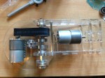
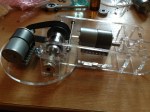
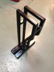
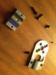
A new RC project is coming! This time, the achieved CAD skills from TU Delft helped me to simulate the entire model and therefore make the optimal design:

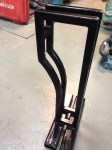
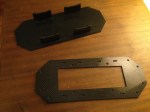
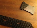
The dxf files for the frame are my own design and can be downloaded for free from here under GNU license. I chose to make the frame out of 2mm carbon fiber because I found cheap sheets on http://www.hobbyking.com. Unfortunately, I couldn’t find a laser that cuts carbon fiber sheets, so I cut them with the Dremel.


Specs:
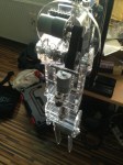
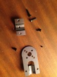
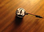
- Motors: 4x3536 NTM (910kV, 350W)
- Props: 4×12″
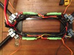
- ESC: 4x30A
- Accu: 5000mA
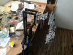
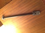
- Frame and booms: Carbon fiber
- Controller: HKPilot 2.7
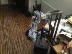
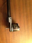
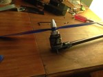
Each motor produces 1.2kg of thrust and the final weight of the aircraft is 3.2kg. It stays in the air very stable because of the 320mm long booms.
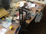
The final product looks like this: