DUT15 drive test

Today I got the opportunity to drive our DUT15! So much power in such a lightweight vehicle. The entire team that worked on this car had a few circuit laps and two acceleration runs. I have to admit though, the amount of acceleration is insane! I am a big guy, but this car still got me to 100km/h in just a bit more than 2 seconds.

Nonetheless, I have to share my crazy driving skills. Not that I am proud of myself or glad that I scratched those expensive carbon fiber wings. Here is what happened.

V1.0

This miniQuad build is meant for racing. My goal is to build a low-budget version of this:

Charpu’s quad is around 1000 ‎€ and I think I can achieve about the same performance with a fourth of that money.

I am using the same technique as I did with the big Quad V2.0. A sandwich frame, but instead of the round profile booms, I am using square profile because it is easier to make the connection between the carbon fibre bars.

Specs:

The dxf files for the frame are my own design and can be downloaded for free from here under GNU license.

Since the quad is built for racing it is calculated to hover at 30% thrust. The total weight of the aircraft is 535g, battery included.

Formula Student experience

One year ago I joined this amazing student team. DUT15 is the name of the car that 80 people worked on so hard to bring it to life. Today I am proud to say that we are the overall winners of FSUK 2015, on the Silverstone circuit and the overall winners of FSG 2015 on the Hockenheim circuit!

SAMSUNG CSC


About the car

atz198.png

DUT is a 4WD electric car, each wheel being powered by a motor.

  • Total weight (no driver): 160kg
  • Motors: 4 x AMK 35kW
  • Accumulator: 7.2kWh LiPo
  • Acceleration: 0-100Km/h in 2.3s

Design presentation:


From sketch to victory

I worked on the car as a part time Powertrain engineer. During the period of 9 months the entire team went through conceptual preliminary and detailed design, as well as manufacturing and testing. During the design phase, I was responsible for the water cooling system of the four motor controllers.  During the manufacturing phase I was in the mechanical crew milling the suspension brackets and lathing the shafts of the car.

updut2

All in all, it was an amazing experience. I improved my design and manufacturing skills and most important, I had a lot of fun building this car!

V2.0

I am creating the second version of the quad because I wasn’t happy with the performance of the first one. It was too heavy for the generated thrust. The 4 NTM 3536 motors were producing only 150% of the aircraft’s weight. That means the quad was hovering at 66% throttle which is not ok for my requirements, since I want to transport a 400g camera onboard.

My plan is to change the battery from a 3S (11.1V) to a 4S (14.8V) and change the propellers to generate more thrust. I also want to minimize the weight, so I am completely changing the frame structure. I am going again for a sandwich structure. I am using the 14mm booms for the main structure, which will be reinforced by the bottom and upper plates made of PCB. By doing this, I will also benefit from the copper paths and thus, have a distribution board for my ESCs.

The dxf files for the frame are my own design and can be downloaded for free from here under GNU license.

SRP rocket

Few days ago I had the amazing opportunity to go to ‘t Harde, at a military base to launch few rockets. Among these was my team’s rocket (John) which was designed and build by Aleksandar Petrov, Chris Niemeijer, Aleksader Parelo, Hardi Njo and myself. The goal was simple, yet challenging: to fire up a rocket up to 1 km with an egg on board and land safely to protect the payload.

And this is what happened (video by Hardi Njo):

Unfortunately, the egg did not survive and that is because the parachute did not deploy, but we did achieve about 800 m of altitude as the rocket was quite stable. That is mostly because of a detailed design in OpenRocket where the CG and the CP were properly placed. Another reason might be the fins that were 3D printed at an accurate angle between each other. The parachute wasn’t supposed to be deployed using pyrotechnics. The cone was meant to be pushed by a spring out of the body. In this way, the airflow had only one job: to open the parachute. This did not happen because of the timing. The spring was released too early, when the rocket was few moments before its apogee and the aerodynamic force was still pressing the cone downwards.

The interesting fact was that the main body of the rocket survived, despite the crash at about 200 km/h with the ground. The conclusion: it was over designed, but it was a fun experience laminating it, layer by layer.

Other rockets taking part to the event:

Frame upgrade & first print

Even from the beginning I didn’t really like the metal bed frame with the threaded rods and nuts, but I chose to build it because it was cheap. So after I finished my printer I started to look up on the internet on how can I improve the quality of the printer. More and more people were complaining about the metal frame which cause alignment issues and vibrations, but no one did anything about it. I couldn’t find any upgrade that could replace the existing frame, so I decided I should take initiative. In fact, this is what an open source project means, I used other people’s work, now it is my time to give something to this society. This is the difference between the old frame and the one I designed:

The dxf files for the frame are my own design and can be downloaded for free from here under GNU license. The CATIA files are also in the repository in case of any further edit.

This bed frame solves the alignment problems and it suits perfectly with the main frame I use. It is now more stable, it has no vibrations and the printig quatily is improved. Please feel free to download the files and laser cut them out of 6mm MDF.

Electronics

The last part of my build deals with electronics, which combines the mechanical movements with the software algorithm that analyse the 3D model. The electronic diagram looks easy:

Source: lh4.googleusercontent.com

This is the RAMPS 1.4 board which can be bought or made. It connects to an Arduino Mega board which has the USB interface for the computer. Except from the two boards, I also needed some powerful drivers. In my opinion, the most important parts of a printer that have to be qualitative are the hot end (I used E3D), the linear bearings (SKF) and the drivers, which are in this case the DRV8825. They have a 1/32 step which increase the resolution of movement, therefore a smoother part results out of the printer.

Change to bowden set-up

Because NEMA 17 weights about 300g, the printer head will have an induced momentum, meaning that it would have not handle the high accelerations that I will need in order to print fast. This is why, I decided to go for a bowden setup and replace the old configuration. This is how it looks now:

IMG_4206

This is a lighter version that has one fan (in the front) for cooling the cold end and 2 smaller fans that will cool down the hot extruded filament. The latter comes through the white teflon pipe being pushed by a stepper motor:

IMG_4219

The parts needed for this conversion can be found here:

In order to push the filament to the hot end, the NEMA motor needs a gear to have grip. I use the MK8 gear and here it is an easy and cheap way to make it.

Frame and mechanics

The frame was cut according to the dimensions from the dxf file and is now ready to support my printer. The order from E3D also arrived with the rest of the parts from the BOM. The only difference from the list is the hot end, because I didn’t want to go for a J-head, but instead I chose the 3mm E3D-V6 since I have heard good things about it.

IMG_3898

IMG_3895

Since I had the plastic gears already included in the printed parts, I chose a direct set-up, meaning that the extruder will stay on top of the hot end, feeding the filament inside. This is not necessary the best solution in my opinion because the printing will have to go slower because of the extra weight added on the x and y-axis.

In the present, the printer started to get a shape and it looks like this:

An extra feature added to this frame is the MF105ZZ, which is a 5mm bearing that will prevent the wobbling of the M5 rod on the z-axis. I find this really important because it makes sense to constrain a spinning rod on both ends and not in only one like the original Prusa.

IMG_3924

Prusa i3 Rework

As 3D printers started to become so popular, I decided that I should have a mini-factory at home. Surfing on the internet, I have found that this model (Prusa i3 Rework) is quite appreciated for a 400€ budget. Moreover, it is an open source project which means I can contribute and develop it in the future.

The BOM can be found here.

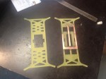
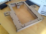
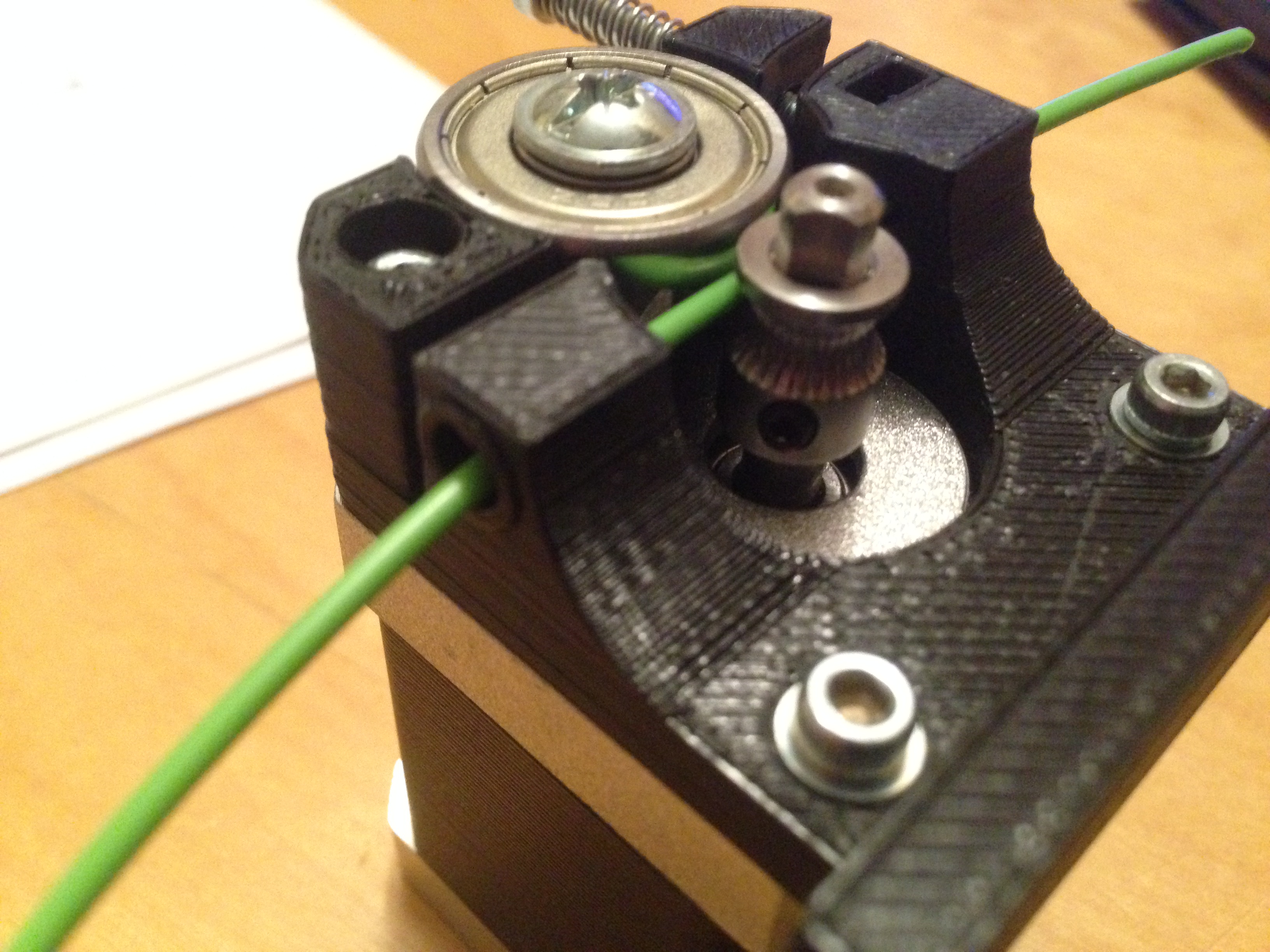
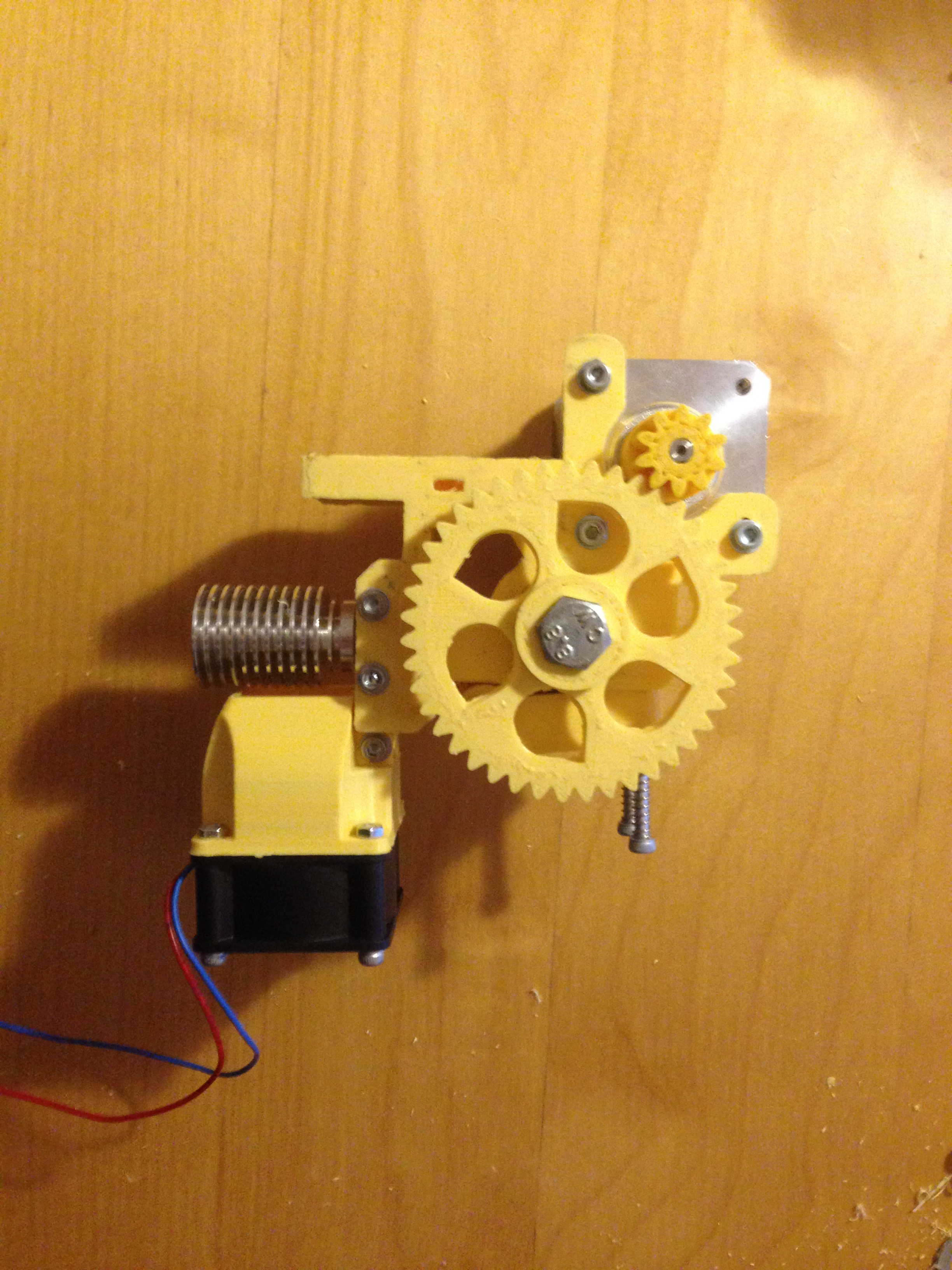
I am posting this today because I just received the printed parts from Ebay as seen below.

IMG_3897

While these parts were shipping to my address, I already bought the rods, screws and nuts from a local hardware store. Parts like electronics, belts, gears, stepper motors or hot end can be found on web sites like this: http://www.e3d-online.com or on other web sites.

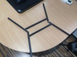
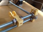
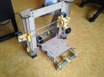
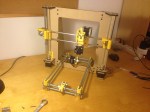
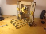
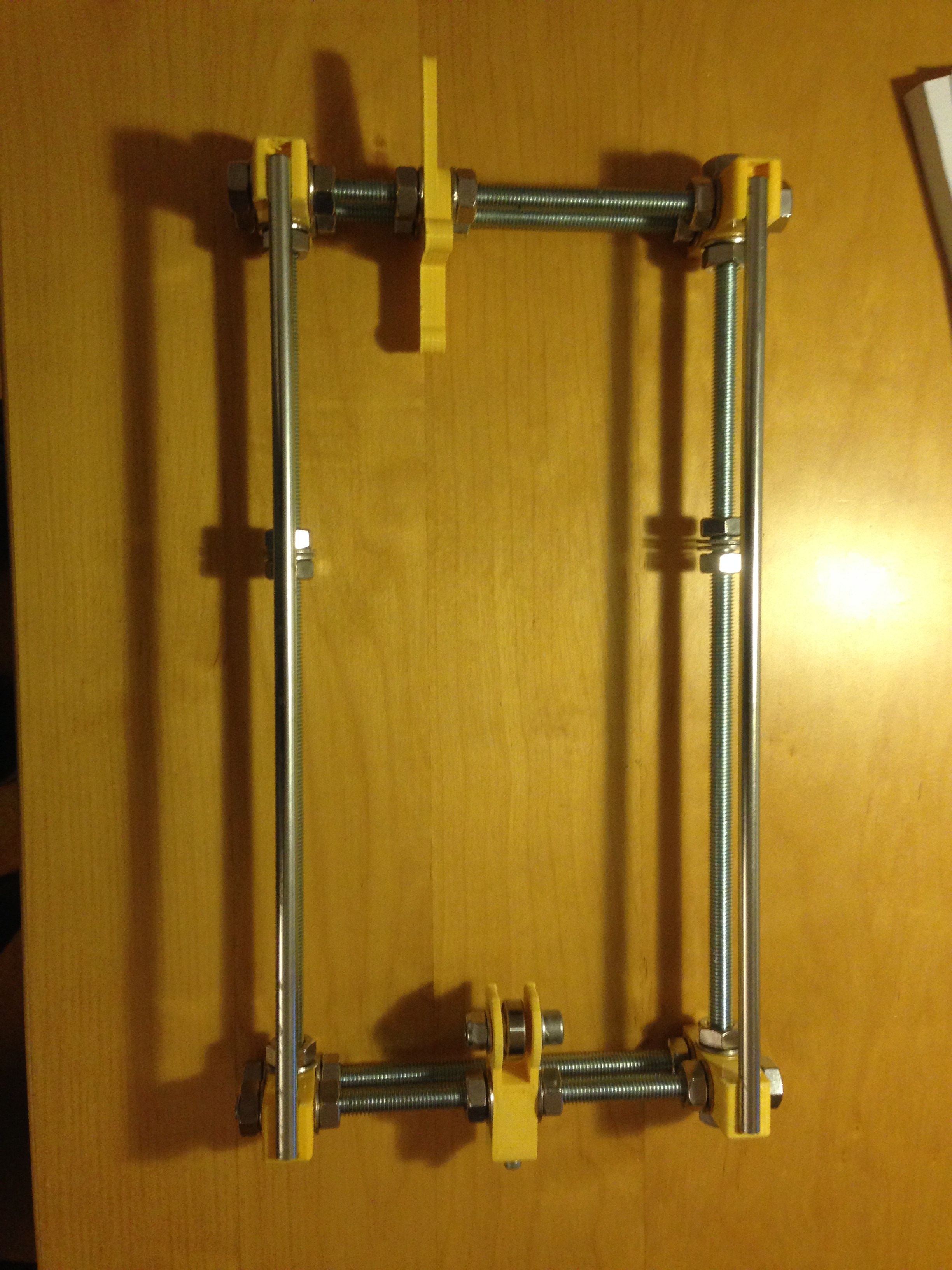
Being enthusiastic about building my own printer, I couldn’t resist to wait until tomorrow, so I already started to build the bed frame.

IMG_3900

The next step would be to order the main frame. On reprap.org it is recommended to buy an aluminium frame which I found to be a bit too expensive. I already found a wood frame project which has extra reinforcements and is build out of 6mm MDF. I have chosen this frame because the MDF is easy to find in any hardware store and because my University provides laser cut services. In this way, I will end up spending less money which can be invested later in important quality parts, such as the hot end.