We did it!


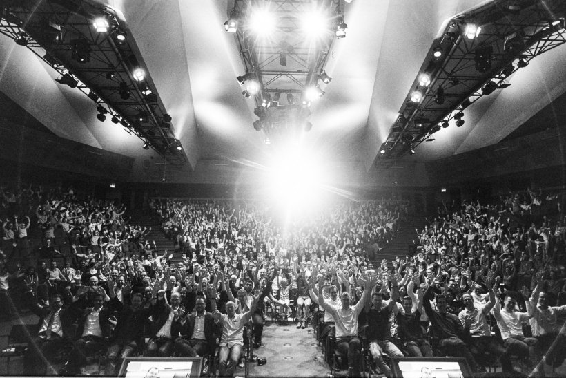
After a week full of ups and downs we managed to finish the race 2nd!

Here is the full story

Part of our team arrived in Los Angeles on the 1st of July to set up a workshop and prepare the vehicle for the day we moved to SpaceX, on the 16th of July. Luckily enough, our sponsor DHL, not only helped us with transporting our pod from the Netherlands to the United States but they also gave us a working space in one of the LAX hangars.

During the competition week 16th – 22nd of July our team had to pass the safety checks imposed by SpaceX in the following order, the last one being the competition day itself, on the 22nd of July

The safety tests

  1. Structural inspection
  2. Mechanical fit check
  3. Navigation
  4. State diagram transition
  5. Functional
  6. External sub-track
  7. Vacuum chamber
  8. Open-air
  9. Final run

We started off on Monday the 16th going through the list and discussing with the SpaceX experts and advisors, trying to get their approvals in order to pass the tests. We managed to pass around two tests per day for the first few days.

It goes down from here

Unfortunately, somewhere mid-week we encountered challenging issues with our main software algorithm and we got stuck at test 5. We worked day and night on trying to solve our problems, but while we were debugging our software and resetting the main board, we had some short circuits. By Thursday, we burned our Hercules board and we had only one left. We ordered more spares, but unfortunately, none of them would have arrived before the competition, so we had to be very careful with that last board.

On Friday night, we were still stuck with the functional test and because we were in a rush and very tired, we burned the last board. At this point, 36 hours before the competition, we almost lost any hope. We were down and I could not believe that after an entire year of hard work, we ended up in this state. It was a terrible night, I couldn’t sleep almost at all.

Rising up

The next day, on Saturday morning, T-24h, we found a working Hercules board in one of our boxes. It was labelled not to be working, but magically enough, it was good to go. At this point, the entire team started working with a lot of energy and enthusiasm, having hope again for the finals.

By mid-day, we fixed all our software problems and we were ready to have the judges asses our pod. We passed the functional test in a few minutes. We run towards the external track and in no-time, the vehicle was set on the rail. This was a big moment for us, to prove that it works. And here is the proof:

Before we could try the same on the 1km long track in the open-air, we had to pass the vacuum chamber test as well. Luckily enough, we could do that in under 2h, as we already had practised the procedure at ESA.

And so we did. By 9pm we passed every single test and we were ready to enter the tube for the first time.

It was an amazing day. In 12h we managed to pass four big tests and qualify for the final race. We had 12 more hours to prepare for that and make sure that everything works perfectly.

The competition day

We had spent all the night before to make sure that we have the right parameters for the launch. Due to the limited testing time that we had on the rail, we had quite some uncertainty. Nonetheless, we were the first team to race on the day followed by EPFL and Warr. We took 30 minutes to set-up the vehicle on the rail and another 30 minutes to pump down to vacuum. The pumps could only bring the pressure down to 0.3bars within that time as we couldn’t afford to delay the entire event.

I go on the microphone 5, 4, 3, 2, 1 GO!… Nothing. Our pod could not start with the parameters for 500km/h (which were never tested in load). We had the backup parameters at hand. The ones that worked the night before. We quickly plugged them in and I go again: 3, 2, 1 GO!… And it goes this time, not to 500km/h, but to 142km/h.

So what happened?

In short, the motor controller overheated and it reached the thermal limit of 80deg C. In these cases, the procedure is to disable the motor and enable the brakes in order to bring the pod to a safe stand-still state.

We learned many things from this project, from each other, from the SpaceX employees during the competition and from the industry. One of the most important thing that I will take home is testing. If we would have had one more day to test the behaviour of the overall system, collect telemetry and understand it, then the race would have been a bit more interesting.

I congratulate Warr from TU Munich for reaching an amazing speed of 467km/h and breaking the speed record and EPFL from Lausanne for reaching 85km/h.

Delft Hyperloop will not give up, because a new team will now continue to push the limits of technology with a new pod, even faster. They now have DH02 from which they can learn a lot.

Hyperloop pod reveal

Amazing audience last week at our pod reveal.  After 10 months of design work, manufacturing and testing I am proud to show you our result. Here is our entire presentation:

Stay posted and follow us on social media to find out what challenges we face up during the SpaceX competition of July 22nd. Part of our team already leaves tomorrow to Los Angeles.

Hyperloop pod vacuum test at ESA

Last week was amazing! Who has the opportunity to do some tests for 10 days and work next to the employees at ESA and ETS? Well, we do!

Our team is proud to have ESA as a partner and we are very grateful for all the support that they provided us at ESTEC, Noordwijk. Our primary objective was to do a full vehicle test and operate it under vacuum conditions. We simulated the environment that the pod will encounter in the SpaceX tube, which is roughly 10mbars and 40deg C.

Since the battery cells don’t suffer vacuum, we need to protect them by maintaining an ambient pressure environment around them. We got all the useful data out, including the pressure in the battery box and the temperature of the different electronic components. This test helped us not only to validate the leak-proof of the case but also to understand how long can our electronics function without convection.

Now our pod is back to the workshop. It took us only a few hours to get it dirty again. Next time I go to ESA I will appreciate more the environment and the clean tools they have.

Press articles: ESA, ETS, International Business Times, Value Walk, ECN Mag, Technology Braking News, Space Mart, Actualidad Aeroespacial, Terra Daily, Cent, Korea IT Times

Hyperloop design presentation

Last night was incredible! 700 people coming at Delft’s theater to watch our design reveal. I very pleased with the reactions I got from the public and I am very encouraged to get back on that stage. Who knows, maybe for a pod reveal? Stay tuned and you’ll find out our top speed soon!
Here is our five months of work represented in one hour. First, you see Edouard presenting our long term vision, next is Maurits with the process we are following and finally you see me explaining the technical part and the pod that will race at the SpaceX competition on July 22nd. Enjoy!

Delft Hyperloop Team

This is our team. 37 people working towards the same goal: Make a positive impact on the future of transportation by building an innovative, fast and scalable vehicle capable of winning the SpaceX Hyperloop Pod Competition III 2018.

25182341_1623277241063492_4526247611226907097_o

I started working on this exciting project full time since August 2017. Every day I wake up with more and more passion for our pod. My task as the CTO of this team is to manage the interfaces between the different departments and assure the quality of our product. At the end of the day, I have to make sure that all the subsystems are assembled into one seamless and fully functional vehicle. For now, the project is confidential until February when we will present our design to the world. Stay tuned and you will find out how we can reach incredible speeds!

Design Synthesis Exercise: Final year project at TU Delft

I graduated! After 3 years I am proud to say that I did my Bachelors of Honours at the Aerospace Engineering faculty of TU Delft.

Today my team and I have finished our final year project. After ten weeks of work we managed to present our design to a large crowd at the yearly DSE symposium. Our team was composed of 9 students and out of 26 teams we were ranked as having the 2nd best design by a jury of several European CEOs and professors form different universities. But what did we do?

19727332_1517172105009449_445776990_o

Under the supervision of Christophe De Wagter we designed a pollinator drone. Why? Because of the need of artificial pollination. Bees are dying and a backup system needs to be set in place from an early stage. One third of your food relies on being pollinated by bees and if no solution mitigates the risk of hunger, people might die in less than 4 years.

We targeted the most profitable crop in the Netherlands, namely the tomato plant. This plant relies on self pollination, meaning that the pollen from the male part is in the same flower as the female part. This process makes the tomato flowers relatively easy to pollinate compared with the vanilla or the cucumber crop where cross pollination processes involve transporting the pollen from a male flower to a different female flower.

Isometric_view.png
APIS – Autonomous Pollination & Imaging System

We started of with three concepts: a flapping wing, a small quad rotor and a big one. Trade-offs were evaluated in order to determine the best concept, and because of the high payload needed to be carried on board, the big quad rotor concept was chosen. Its name is APIS and it fits in a 30 by 30 cm box, with a weight lower than 250 g. It can fly autonomously for 10 to 12 minutes using the UWB (Ultra-Wide-Band) for indoor navigation, or the stereo vision for obstacle avoidance. The full system consists of 64 APIS and 8 ground stations and it is able to pollinate a 4 hectare tomato greenhouse every 3 days.

How can APIS pollinate like a bee? Well, it’s just inspired by bees. Studying them closely, we found out that the 100 Hz flapping frequency of a bee is enough to shake the flower and move the pollen to the right place. Therefore, we designed a blower that will target the flowers one by one with a 10 m/s air jet. This jet can induce vortex shedding to the stem of the flower and thus, vibrate it with the right frequency.

If you would like to dive more into the technical part of the detailed design and answer questions like how does the propeller wake interfere with the blower or what kind of electronics and algorithms can be used for the sensors and for navigating inside a crowded place like a greenhouse, then you can read the attached 150 page report made by our team: Greenhouse Pollinator Drone Final Report. Make sure you also check the design video below.

“Scan and Grab” – autonomous robotic arm

Another late night, another hackathon. This time our team came up second on the iNTU Hackathon podium.

We created an autonomous robotic arm designed to detect and pickup simple objects in the area in front of it. The robot firstly performs a fast scan by rotating an IR distance sensor to detect if there is any objects in front of it. If there is an object, the robot will perform another scan to more accurately estimate the Cartesian coordinates of the object. When it has this information it will attempt to pick the object up with its claw and move it to the trash bin.

This is how it works:


The arm itself has 5 Dynamixel AX-12 servos and one AX-18 providing for 4 degrees of freedom. At its base it has a Sharp GP2D12 sensor. The servos are commanded directly from a laptop running a python script. The script gets input from the Arduino board which digitizes the analog output of the IR sensor. Outlier detection and averaging are used to make the signal more reliable. Furthermore, the signal is processed into distance by making use of interpolating functions that were determined from a calibration test. Distance data is then processed to estimate the size of the object. Location and size is then used by the program to command the arm to grasp and lift the object. In order to achieve this, firstly, a forward kinematic model was validated, followed by the implementation of the inverse kinematic model in a Python function. The claw is 3D printed and adapted from an open source project.

Try it out: GitHub Repo

Experiments DAQ

It wasn’t much until I had the first droplets on my screen (as pixels of course). Thanks to prof. Schrijer, we were able to quickly find out the right camera settings for this setup. It was about a PCO Sensicam with a Nikon ED 180mm and 68mm extension tubes. Because the lenses were rather far from the image sensor, the f stop was set to 4.

The software used to acquire the images was Davis 8.1.5 and the pressure upsetream the injector was recorded by Labview 15.

When looking at the droplets, it is important to freeze the jet as much as possible in order to reduce the blur. One could say that the shutter of the above mentioned camera would be enough, but in fact, is not that fast. In my case a light source was a better option. It can be triggered extremely fast with a perfect synchronization with the camera. The main advantage is that the pulse duration is much shorter than 1μs i.e. the exposure of the camera.

Now looking at the light position with respect to the camera, it is important to understand the goal of this measurements. We want to look at the droplet size and this means that they must be imaged in a high contrast homogeneous way. If the light source is placed behind the camera, the drops will be seen as bright spots only in the middle creating a non-homogeneous area since they are in fact, small spheres. This problem is solved using shadowgraphy, which means that the light source is placed facing the camera. In this way, the camera will see light everywhere except from the regions where droplets/liquid is between the light and the camera.

The difference between lighting from behind/above the camera and shadowgraphy can be seen in the images below.

And the full setup:

In case you were wondering what happened with the injector, I switched to a pintle as I could not achieve atomization with the plain orifice with only 10 bar. The pintle injector was simply made by centering a flat screw inside a diverging fitting.

20160714_191255.jpg

Experimental setup

Yesterday I finished the first part of the setup i.e. the feed system: from the air supply to the water tank to the injector. Here are some pictures:

The air supply in the Aerodynamics lab is 10 bar. The gas passes a manual valve, a check valve, a relief valve set just above 10 bar and a regulator with a range of 1-10 bar. This is what you can see on the main wood panel. On its other side, the water tank is pressurized by the regulated air and the liquid goes towards the injector. It first passes through a pressure transducer and a solenoid valve connected to the electronic box. This consists of a small voltage divider and a data acquisition board (NI 6211). The pressure is displayed and the valve is controlled by the control panel made in LabView.

After the safety check is passed, next week, Prof. Ferry Schrijer will help me with the main part of this project i.e. measuring the size of the droplets. Since the jet velocity is 30 m/s and the size of the droplets is expected to be around 50 μm, the taken pictures must be completely frozen in order to collect relevant data. This cannot be done by the shutter of the high speed camera as it is too slow, but instead, a light source will be used for a shorter period (in the order of ns). More about the equipment will follow in a later post.

Sizing the droplets of a rocket injector

Last year, around October, I have been admitted to the Honours Programme by TU Delft’s faculty of Aerospace Engineering. This programme consists of extracurricular courses (such as Personal Leadership, Cybersecurity, Design Thinking, etc.) and a research project worth of 13 ECTS. The latter has been a challenge for me to choose because I was told that I can take any domain in our faculty to dig into. After several months of visiting different professors, I made my choice of working in Space Engineering with Prof. Barry Zandbergen, who is now my supervisor for the current research.

So what am I doing specifically? I can’t just say I am a space engineer who plays with rockets in his spare time (ok, maybe sometimes). The goal of this research is to characterize the droplets of a plain orifice rocket injector. Here is my literature study.

So why is this so important? There is an optimum when it comes to the size/volume of a droplet at a certain distance from the injector. If the droplet is too small, it will evaporate quickly, before penetrating into the combustion chamber. If the droplet is too big, the engine overall will not reach its maximum efficiency.

In order to achieve the objective, experiments are to be held as the behavior of the atomization process is non-linear and models are very hard to predict. Therefore in my experiments, water will be emerged through a simple injector and pictures will be taken at different upstream pressures. I will keep you posted with the experimental setup and the final results.