Frame upgrade & first print

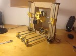
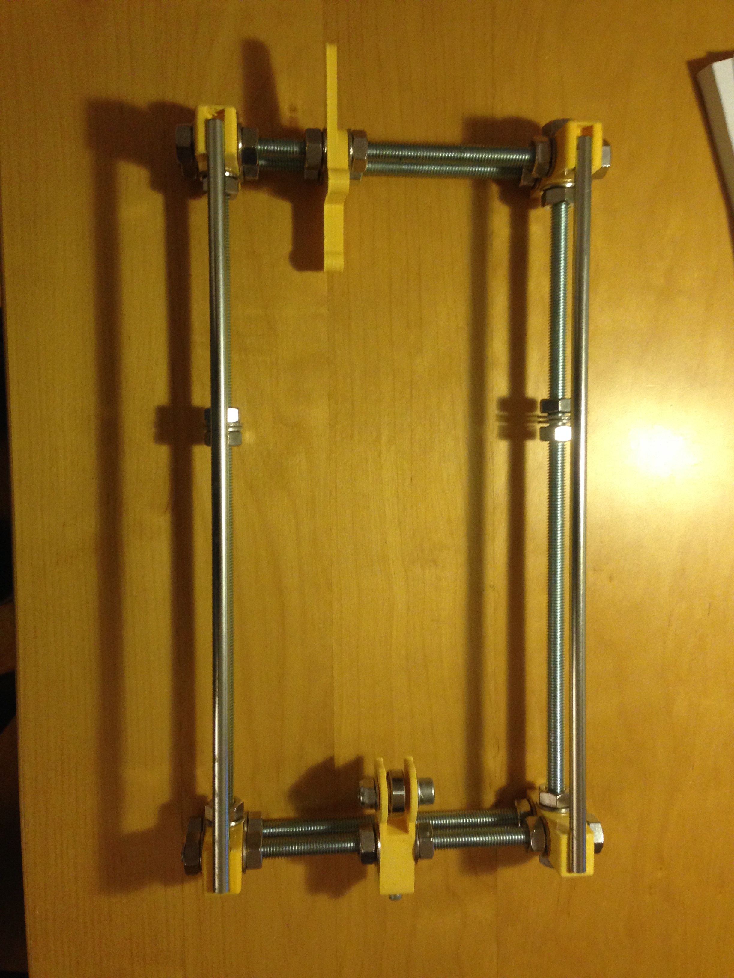
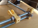
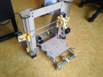
Even from the beginning I didn’t really like the metal bed frame with the threaded rods and nuts, but I chose to build it because it was cheap. So after I finished my printer I started to look up on the internet on how can I improve the quality of the printer. More and more people were complaining about the metal frame which cause alignment issues and vibrations, but no one did anything about it. I couldn’t find any upgrade that could replace the existing frame, so I decided I should take initiative. In fact, this is what an open source project means, I used other people’s work, now it is my time to give something to this society. This is the difference between the old frame and the one I designed:

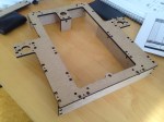
The dxf files for the frame are my own design and can be downloaded for free from here under GNU license. The CATIA files are also in the repository in case of any further edit.

This bed frame solves the alignment problems and it suits perfectly with the main frame I use. It is now more stable, it has no vibrations and the printig quatily is improved. Please feel free to download the files and laser cut them out of 6mm MDF.

Electronics

The last part of my build deals with electronics, which combines the mechanical movements with the software algorithm that analyse the 3D model. The electronic diagram looks easy:

Source: lh4.googleusercontent.com

This is the RAMPS 1.4 board which can be bought or made. It connects to an Arduino Mega board which has the USB interface for the computer. Except from the two boards, I also needed some powerful drivers. In my opinion, the most important parts of a printer that have to be qualitative are the hot end (I used E3D), the linear bearings (SKF) and the drivers, which are in this case the DRV8825. They have a 1/32 step which increase the resolution of movement, therefore a smoother part results out of the printer.

Change to bowden set-up

Because NEMA 17 weights about 300g, the printer head will have an induced momentum, meaning that it would have not handle the high accelerations that I will need in order to print fast. This is why, I decided to go for a bowden setup and replace the old configuration. This is how it looks now:

IMG_4206

This is a lighter version that has one fan (in the front) for cooling the cold end and 2 smaller fans that will cool down the hot extruded filament. The latter comes through the white teflon pipe being pushed by a stepper motor:

IMG_4219

The parts needed for this conversion can be found here:

In order to push the filament to the hot end, the NEMA motor needs a gear to have grip. I use the MK8 gear and here it is an easy and cheap way to make it.

Frame and mechanics

The frame was cut according to the dimensions from the dxf file and is now ready to support my printer. The order from E3D also arrived with the rest of the parts from the BOM. The only difference from the list is the hot end, because I didn’t want to go for a J-head, but instead I chose the 3mm E3D-V6 since I have heard good things about it.

IMG_3898

IMG_3895

Since I had the plastic gears already included in the printed parts, I chose a direct set-up, meaning that the extruder will stay on top of the hot end, feeding the filament inside. This is not necessary the best solution in my opinion because the printing will have to go slower because of the extra weight added on the x and y-axis.

In the present, the printer started to get a shape and it looks like this:

An extra feature added to this frame is the MF105ZZ, which is a 5mm bearing that will prevent the wobbling of the M5 rod on the z-axis. I find this really important because it makes sense to constrain a spinning rod on both ends and not in only one like the original Prusa.

IMG_3924

Prusa i3 Rework

As 3D printers started to become so popular, I decided that I should have a mini-factory at home. Surfing on the internet, I have found that this model (Prusa i3 Rework) is quite appreciated for a 400€ budget. Moreover, it is an open source project which means I can contribute and develop it in the future.

The BOM can be found here.

I am posting this today because I just received the printed parts from Ebay as seen below.

IMG_3897

While these parts were shipping to my address, I already bought the rods, screws and nuts from a local hardware store. Parts like electronics, belts, gears, stepper motors or hot end can be found on web sites like this: http://www.e3d-online.com or on other web sites.

Being enthusiastic about building my own printer, I couldn’t resist to wait until tomorrow, so I already started to build the bed frame.

IMG_3900

The next step would be to order the main frame. On reprap.org it is recommended to buy an aluminium frame which I found to be a bit too expensive. I already found a wood frame project which has extra reinforcements and is build out of 6mm MDF. I have chosen this frame because the MDF is easy to find in any hardware store and because my University provides laser cut services. In this way, I will end up spending less money which can be invested later in important quality parts, such as the hot end.