Frame and mechanics

The frame was cut according to the dimensions from the dxf file and is now ready to support my printer. The order from E3D also arrived with the rest of the parts from the BOM. The only difference from the list is the hot end, because I didn’t want to go for a J-head, but instead I chose the 3mm E3D-V6 since I have heard good things about it.

IMG_3898

IMG_3895

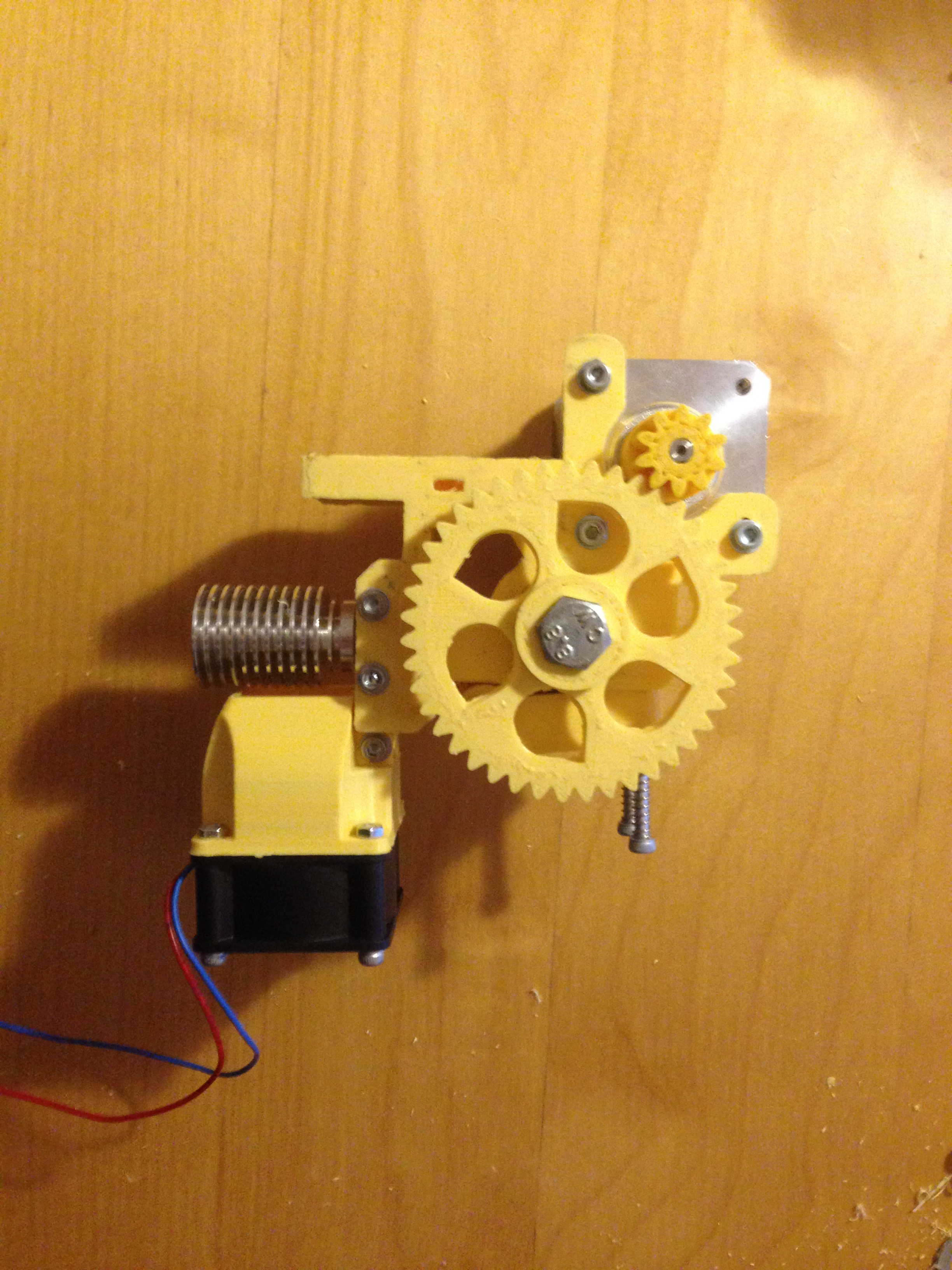
Since I had the plastic gears already included in the printed parts, I chose a direct set-up, meaning that the extruder will stay on top of the hot end, feeding the filament inside. This is not necessary the best solution in my opinion because the printing will have to go slower because of the extra weight added on the x and y-axis.

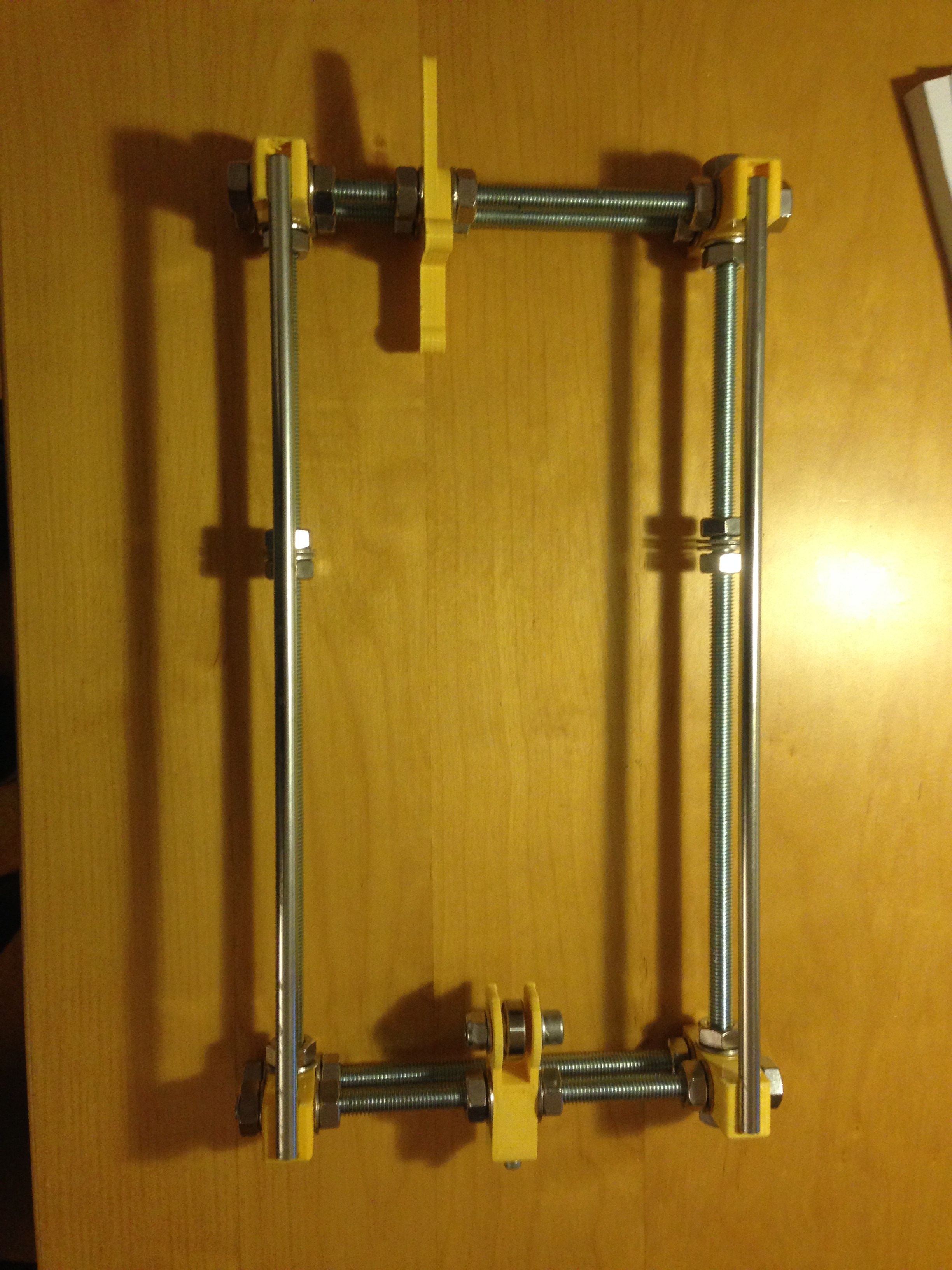
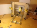
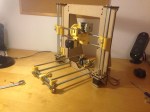
In the present, the printer started to get a shape and it looks like this:

An extra feature added to this frame is the MF105ZZ, which is a 5mm bearing that will prevent the wobbling of the M5 rod on the z-axis. I find this really important because it makes sense to constrain a spinning rod on both ends and not in only one like the original Prusa.

IMG_3924

Prusa i3 Rework

As 3D printers started to become so popular, I decided that I should have a mini-factory at home. Surfing on the internet, I have found that this model (Prusa i3 Rework) is quite appreciated for a 400€ budget. Moreover, it is an open source project which means I can contribute and develop it in the future.

The BOM can be found here.

I am posting this today because I just received the printed parts from Ebay as seen below.

IMG_3897

While these parts were shipping to my address, I already bought the rods, screws and nuts from a local hardware store. Parts like electronics, belts, gears, stepper motors or hot end can be found on web sites like this: http://www.e3d-online.com or on other web sites.

Being enthusiastic about building my own printer, I couldn’t resist to wait until tomorrow, so I already started to build the bed frame.

IMG_3900

The next step would be to order the main frame. On reprap.org it is recommended to buy an aluminium frame which I found to be a bit too expensive. I already found a wood frame project which has extra reinforcements and is build out of 6mm MDF. I have chosen this frame because the MDF is easy to find in any hardware store and because my University provides laser cut services. In this way, I will end up spending less money which can be invested later in important quality parts, such as the hot end.

Xtion Arm v1.0

Last Christmas, I received a special gift from my parents. It was a sensor called Xtion from Asus, specially designed for developers. It’s actually a web cam and at the same time a IR cam (for depth) which simulates a 3D vision. It is very similar to Kinect sensor, but the Asus’s version is more flexible from the OS point of view. I am interested in working in Linux (Ubuntu), so this would be the perfect sensor for me.

As I am a beginner at this subject, I have started with different tutorials about Computer Vision and Body Tracking (OpenNI). After several weeks of practice, I made up my mind about how to use this sensor. I built a robotic arm which executes simultaneously, that is in real-time, the movements of my physical arm. I called it “The Xtion Arm”.

Here is my first version:

It is made by plexiglass (4 mm) and has 2 servos for the two joints (elbow and shoulder).

My movements are recorded by Asus Xtion and processed in Processing software which transfers the coordinates of the two points (joints) through a specific port to Arduino software which converts the coordinates of the 3-axis into angular dimensions. These values are sent to Arduino board which commands the servos.

In order for the software to perform this, I have written 3 applications. The first one is called “the Server”, it is developed in Processing and it gets the coordinates in “real world” dimensions. The second application is called “the Client”. The transmission of 9600 bits/s between Server and Client can be achieved either by serial (local: both arm and sensor are connected to the same computer) or via the Internet (sensor+Server on computer 1 and Xtrion Arm+Client on computer 2). The third application is Arduino, it communicates with the Client and sends values to servos. All these codes are published on my GitHub account here.