This miniQuad build is meant for racing. My goal is to build a low-budget version of this:
Charpu’s quad is around 1000 € and I think I can achieve about the same performance with a fourth of that money.
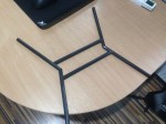
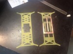
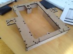
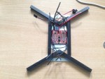
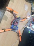
I am using the same technique as I did with the big Quad V2.0. A sandwich frame, but instead of the round profile booms, I am using square profile because it is easier to make the connection between the carbon fibre bars.


Specs:
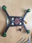
- Motors: 4x 2204 Multistar Elite (2300kV, 130W)
- Props: 4×5″
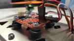
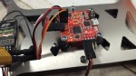
- ESC: Favourite Sky 4 in 1 (12A)
- Accu: 1100mA
- Frame and booms: Allu and carbon fiber
- Controller: Acro Naze 32
The dxf files for the frame are my own design and can be downloaded for free from here under GNU license.
Since the quad is built for racing it is calculated to hover at 30% thrust. The total weight of the aircraft is 535g, battery included.