Experiments DAQ

It wasn’t much until I had the first droplets on my screen (as pixels of course). Thanks to prof. Schrijer, we were able to quickly find out the right camera settings for this setup. It was about a PCO Sensicam with a Nikon ED 180mm and 68mm extension tubes. Because the lenses were rather far from the image sensor, the f stop was set to 4.

The software used to acquire the images was Davis 8.1.5 and the pressure upsetream the injector was recorded by Labview 15.

When looking at the droplets, it is important to freeze the jet as much as possible in order to reduce the blur. One could say that the shutter of the above mentioned camera would be enough, but in fact, is not that fast. In my case a light source was a better option. It can be triggered extremely fast with a perfect synchronization with the camera. The main advantage is that the pulse duration is much shorter than 1μs i.e. the exposure of the camera.

Now looking at the light position with respect to the camera, it is important to understand the goal of this measurements. We want to look at the droplet size and this means that they must be imaged in a high contrast homogeneous way. If the light source is placed behind the camera, the drops will be seen as bright spots only in the middle creating a non-homogeneous area since they are in fact, small spheres. This problem is solved using shadowgraphy, which means that the light source is placed facing the camera. In this way, the camera will see light everywhere except from the regions where droplets/liquid is between the light and the camera.

The difference between lighting from behind/above the camera and shadowgraphy can be seen in the images below.
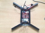
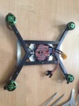
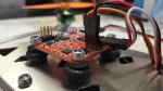
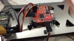
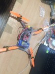
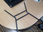
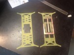
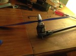
And the full setup:

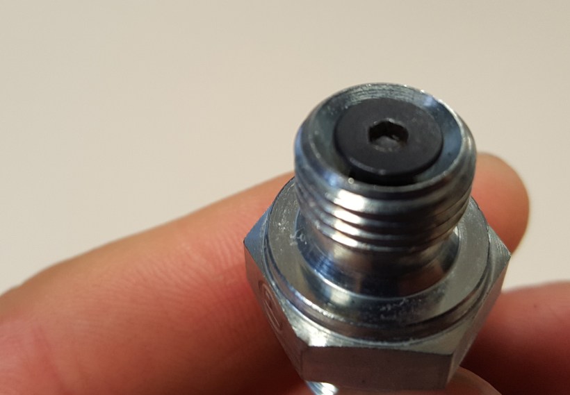
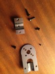
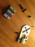
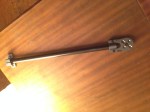
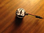
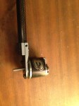
In case you were wondering what happened with the injector, I switched to a pintle as I could not achieve atomization with the plain orifice with only 10 bar. The pintle injector was simply made by centering a flat screw inside a diverging fitting.

20160714_191255.jpg

Experimental setup

Yesterday I finished the first part of the setup i.e. the feed system: from the air supply to the water tank to the injector. Here are some pictures:

The air supply in the Aerodynamics lab is 10 bar. The gas passes a manual valve, a check valve, a relief valve set just above 10 bar and a regulator with a range of 1-10 bar. This is what you can see on the main wood panel. On its other side, the water tank is pressurized by the regulated air and the liquid goes towards the injector. It first passes through a pressure transducer and a solenoid valve connected to the electronic box. This consists of a small voltage divider and a data acquisition board (NI 6211). The pressure is displayed and the valve is controlled by the control panel made in LabView.

After the safety check is passed, next week, Prof. Ferry Schrijer will help me with the main part of this project i.e. measuring the size of the droplets. Since the jet velocity is 30 m/s and the size of the droplets is expected to be around 50 μm, the taken pictures must be completely frozen in order to collect relevant data. This cannot be done by the shutter of the high speed camera as it is too slow, but instead, a light source will be used for a shorter period (in the order of ns). More about the equipment will follow in a later post.

Sizing the droplets of a rocket injector

Last year, around October, I have been admitted to the Honours Programme by TU Delft’s faculty of Aerospace Engineering. This programme consists of extracurricular courses (such as Personal Leadership, Cybersecurity, Design Thinking, etc.) and a research project worth of 13 ECTS. The latter has been a challenge for me to choose because I was told that I can take any domain in our faculty to dig into. After several months of visiting different professors, I made my choice of working in Space Engineering with Prof. Barry Zandbergen, who is now my supervisor for the current research.

So what am I doing specifically? I can’t just say I am a space engineer who plays with rockets in his spare time (ok, maybe sometimes). The goal of this research is to characterize the droplets of a plain orifice rocket injector. Here is my literature study.

So why is this so important? There is an optimum when it comes to the size/volume of a droplet at a certain distance from the injector. If the droplet is too small, it will evaporate quickly, before penetrating into the combustion chamber. If the droplet is too big, the engine overall will not reach its maximum efficiency.

In order to achieve the objective, experiments are to be held as the behavior of the atomization process is non-linear and models are very hard to predict. Therefore in my experiments, water will be emerged through a simple injector and pictures will be taken at different upstream pressures. I will keep you posted with the experimental setup and the final results.

V1.0

This miniQuad build is meant for racing. My goal is to build a low-budget version of this:

Charpu’s quad is around 1000 ‎€ and I think I can achieve about the same performance with a fourth of that money.

I am using the same technique as I did with the big Quad V2.0. A sandwich frame, but instead of the round profile booms, I am using square profile because it is easier to make the connection between the carbon fibre bars.

Specs:

The dxf files for the frame are my own design and can be downloaded for free from here under GNU license.

Since the quad is built for racing it is calculated to hover at 30% thrust. The total weight of the aircraft is 535g, battery included.

V2.0

I am creating the second version of the quad because I wasn’t happy with the performance of the first one. It was too heavy for the generated thrust. The 4 NTM 3536 motors were producing only 150% of the aircraft’s weight. That means the quad was hovering at 66% throttle which is not ok for my requirements, since I want to transport a 400g camera onboard.

My plan is to change the battery from a 3S (11.1V) to a 4S (14.8V) and change the propellers to generate more thrust. I also want to minimize the weight, so I am completely changing the frame structure. I am going again for a sandwich structure. I am using the 14mm booms for the main structure, which will be reinforced by the bottom and upper plates made of PCB. By doing this, I will also benefit from the copper paths and thus, have a distribution board for my ESCs.

The dxf files for the frame are my own design and can be downloaded for free from here under GNU license.

SRP rocket

Few days ago I had the amazing opportunity to go to ‘t Harde, at a military base to launch few rockets. Among these was my team’s rocket (John) which was designed and build by Aleksandar Petrov, Chris Niemeijer, Aleksader Parelo, Hardi Njo and myself. The goal was simple, yet challenging: to fire up a rocket up to 1 km with an egg on board and land safely to protect the payload.

And this is what happened (video by Hardi Njo):

Unfortunately, the egg did not survive and that is because the parachute did not deploy, but we did achieve about 800 m of altitude as the rocket was quite stable. That is mostly because of a detailed design in OpenRocket where the CG and the CP were properly placed. Another reason might be the fins that were 3D printed at an accurate angle between each other. The parachute wasn’t supposed to be deployed using pyrotechnics. The cone was meant to be pushed by a spring out of the body. In this way, the airflow had only one job: to open the parachute. This did not happen because of the timing. The spring was released too early, when the rocket was few moments before its apogee and the aerodynamic force was still pressing the cone downwards.

The interesting fact was that the main body of the rocket survived, despite the crash at about 200 km/h with the ground. The conclusion: it was over designed, but it was a fun experience laminating it, layer by layer.

Other rockets taking part to the event:

V1.0

A new RC project is coming! This time, the achieved CAD skills from TU Delft helped me to simulate the entire model and therefore make the optimal design:

QuadDrawing-page-001BottomFrameDrawing-page-001

The dxf files for the frame are my own design and can be downloaded for free from here under GNU license. I chose to make the frame out of 2mm carbon fiber because I found cheap sheets on http://www.hobbyking.com. Unfortunately, I couldn’t find a laser that cuts carbon fiber sheets, so I cut them with the Dremel.

Specs:

  • Motors: 4x3536 NTM (910kV, 350W)
  • Props: 4×12″
  • ESC: 4x30A
  • Accu: 5000mA
  • Frame and booms: Carbon fiber
  • Controller: HKPilot 2.7

Each motor produces 1.2kg of thrust and the final weight of the aircraft is 3.2kg. It stays in the air very stable because of the 320mm long booms.

The final product looks like this:

IMG_3750

V1.0

After the flying wing project from TU Delft – semester 1, I decided I should build my own wing with the skills achieved. So I designed it with the following specifications:

  • Wing span: 8500mm
  • Sweep angle: 30°
  • Taper ratio: 1.2
  • Propeller: 8″
  • Motor: 1400kV, 210W
  • Accumulator: 2x3S (11.1V) 1100mA

And before the first crash:

IMG_3468

Unfortunately, I couldn’t film the crashes but I can tell that I had a lot of fun building and piloting it.