Xtion Arm v1.0

Last Christmas, I received a special gift from my parents. It was a sensor called Xtion from Asus, specially designed for developers. It’s actually a web cam and at the same time a IR cam (for depth) which simulates a 3D vision. It is very similar to Kinect sensor, but the Asus’s version is more flexible from the OS point of view. I am interested in working in Linux (Ubuntu), so this would be the perfect sensor for me.

As I am a beginner at this subject, I have started with different tutorials about Computer Vision and Body Tracking (OpenNI). After several weeks of practice, I made up my mind about how to use this sensor. I built a robotic arm which executes simultaneously, that is in real-time, the movements of my physical arm. I called it “The Xtion Arm”.

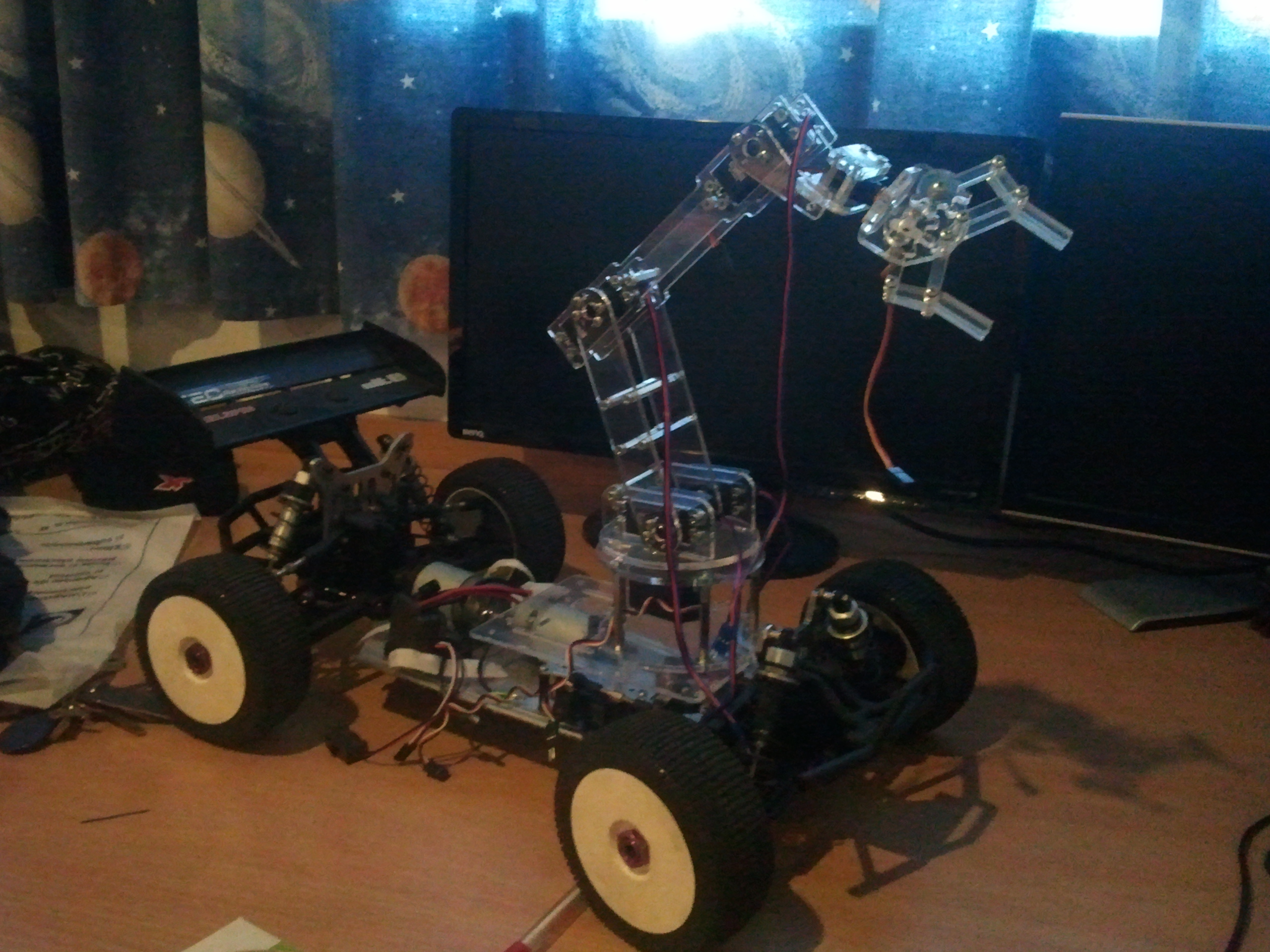
Here is my first version:

It is made by plexiglass (4 mm) and has 2 servos for the two joints (elbow and shoulder).

My movements are recorded by Asus Xtion and processed in Processing software which transfers the coordinates of the two points (joints) through a specific port to Arduino software which converts the coordinates of the 3-axis into angular dimensions. These values are sent to Arduino board which commands the servos.

In order for the software to perform this, I have written 3 applications. The first one is called “the Server”, it is developed in Processing and it gets the coordinates in “real world” dimensions. The second application is called “the Client”. The transmission of 9600 bits/s between Server and Client can be achieved either by serial (local: both arm and sensor are connected to the same computer) or via the Internet (sensor+Server on computer 1 and Xtrion Arm+Client on computer 2). The third application is Arduino, it communicates with the Client and sends values to servos. All these codes are published on my GitHub account here.

Generator module

Two months ago, I was accepted for an internship at Proenerg (a company which focuses on power generators). Initially, I was there to see how a company is run and quite soon I become a part of their workshop team.

After only one week, I got involved in one of their new projects: a module for a generator which would charge the batteries more effectivly. This project was ordered by one of the most important clients who wanted 100 modules + generators. I decided to jump in and design a prototype based on Arduino board.

Batteries, in general, have a certain voltage when are fully charged (eg.24V) and when they are discharged, batts have a lower value (eg. 20 V). Starting from this fact, my prototype was meant to have the following specifications:

  1. When tension reaches the bottom level, the module should close the contact into a relay in order to start the generator which is connected to a charger that would fully charge the batteries.
  2. The module would monitor the batteries and would run the following algorithm:
  • If (V min < V monitored < V max) does nothing;
  • When (V monitored <= V min) close the relay;
  • When (V monitored >= V max) relay releases;

After two weeks I came up with an Arduino shield which worked properly and passed the tests. Here is the algorithm.

The board (the module) has:

  • a voltage divider in order to scale the battery voltage from 24 V down to 5 V (this is the maximum value which Arduino reads on each analog port);
  • a contact relay which is closed when the generator starts;
  • a relay for the electric starter motor which is closed for maximum 3 seconds and only after the contact is on;
  • an alarm relay which closes after 5 failures in starting the generator;
  • a 240 V relay which check the generator’s status (if it is on and charging the batteries or not).

The client was pleased with my prototype and the technicians and electricians helped me to develop the project. A production line was put in place and the integral order of 100 modules and generators was executed. I was very proud of this, as every single circuit board has a part of my innovation built-in it.

Android’s head

After my success with Spy Robot I decided to put together all my projects in one in order to create an Android. The purpose of this project is to control a humanlike robot. This idea comes from what I’ve done with the pan & tilt system which imitates a human neck. If I place the IMU sensor on my head, it will send my head’s coordinates and position to the servos which control the camera. In this way, the Android’s head (camera) is moving simultaneously with my head, recording and streaming in real-time the images. In this way, it gives me the opportunity to collect data from the place where the Android is sent.

I divided the Android into three smaller projects:

  • Head;
  • Arms;
  • Legs.

Next year, I will design and build one of the Android’s arm, which would be one of the most important abilities of the robot.

Spy Robot v2.0

Spy Robot v2.0 is a better version from two points of view: the facilities and the platform.

Facilities

It has the main functions which the previous version also had (collecting data about temperature, humidity and pressure, video and audio streaming). Furthermore, I have attached a robotic arm in order to grasp the objects if I want to. It has 4 joints (6 servos) which are connected to a 2.4 Ghz receiver and controlled by a remote control.

SAMSUNG

The Platform

I used my RC car (electrical version) as it is bigger and designed for off-road.

The final version, ready for the National Contest:

SAMSUNG

Spy Robot v1.0

Everything started from the desire of exploring new territories and collecting data. I chose a RC car as a platform whereon I have attached an Arduino Uno board, temperature, humidity and pressure sensors and a pan & tilt system (2 servos). This system has a web cam holder in order to collect videos and images through a smart phone using Skype. The pan & tilt system is controlled by a Wii nunchuck in real-time. More information about this topic in this tutorial.

SAMSUNG

The communication between Spy Robot and me is achieved by means of two Arduino boards (one placed on the platform and the other one connected to my PC)  which see each other via bluetooth. The video is transferred separately using Skype. Thus, I can see what Spy Robot sees, by controlling its eyes (the camera -smart phone-) with the Wii nunchuck. Meanwhile, I can analyse the information collected from sensors (also in real-time) on the terminal.

SAMSUNG

Yesterday I won the first prize in the regional stage of robotics contest for my robot and I qualified for “Infoeducatie” National Contest, robotics section that would take place in two months. To this respect, I intend to add an arm to my robot, in order to be able to grasp objects that Spy Robot sees during its explorations.

Electrical & cooling system

I had some issues with the electrical system as the old motorcycle had many sensors and lights which are unuseful for me, but after consulting the electrical diagram, everything was fine. I have eliminated the extra wires and after a few hours I have simplified the diagram by 60%.

Before:schema originala

After:schema.2

I did the wiring and as a result, the engine started!

As far as the cooling system is concerned, I attached a water radiator taken from a generator. I placed it at the back, but it will be assisted by an Audi fan in order to maintain the air flow.

photo(2)

Transmission

A few days ago I received the 50 mm diameter bar ordered at the turner, with the proper dimensions I have designed. The ends of the bar are threaded in order to match with the Ford Mondeo II hub carrier secured with nuts. It has also a specific dimension somewhere in the middle for the mid-bearing and the brake disc. The wheel gear is at a third from the left end of the bar and it is also custom-made in order to have a specific power ratio and reduce the speed. The original toothed wheel had 38 teeth and because I needed more torque power I replaced it with a 60 teeth one.

photo

Now, I have to add a 12 teeth wheel as a tentioner for my transmission. I want to do this in order to maintain the chain tensed even in off-road situations.

Steering system & Suspension

This has been the most difficult part so far as I had to adjust every piece in order to fit to my project. I bought some parts such as the front suspension and wheels, steering knuckles, steering box, steering wheel and the strut bar from a Tico car. I have chosen these parts because Tico has MacPherson suspension which is very easy to implement.

SAMSUNG SAMSUNG

I have also attached the pedals from an old Dacia.

Until now, the steering is responsive, the geometry is ok and I shouldn’t have any problems in the future.

Engine

I have been searching for a suitable engine since I bought the plans, but last week I found one laying in a garage. It is a Kawasaki ZX600 motorcycle (Kawasaki Ninja ZX-6R) from ’98 which has incurred an accident. I paid for it 400 €. The front is undone, but the engine is in perfect condition. It has 10.00 km, 75 kW (100 hp) @ 12500 rpm. I chose it not only because it is compact and has a 6-gear gearbox included, but it is powerful at the same time.

SAMSUNG

I have designed and build a framework for it in order to be easily unmounted and to have fully access to it for further changes.